I've installed more dual-battery systems than I can count. Twelve years in the shop, plus another six on my own rigs and guiding other people's. I've done them right, and I've done them wrong. I've seen systems that ran for a decade without a hiccup, and I've seen systems that melted down before the owner made it home from the install.
Here's the thing about dual-battery systems: they're not complicated. The basic concept is simple — two batteries, an isolator, some cable, and a few fuses. But the difference between a system that works and a system that catches fire is in the details. Wire gauge. Fuse placement. Grounding. Component selection.
Get any of those wrong, and you're not just dealing with a dead battery. You're dealing with a melted harness, a dead short, or a fire.
I've got the melted parts on my wall to prove it.
Why You Need a Dual-Battery System
Before we get into the how, let's talk about the why.
A dual-battery system does one thing: it separates your starter battery from your accessory loads. The starter battery is for starting the engine. The auxiliary battery (sometimes called the "house" battery) is for running your fridge, lights, air compressor, radio, and whatever else you plug in when the engine is off.
Without a dual-battery system, every accessory you run drains your starter battery. Run the fridge overnight, and you might wake up to a dead battery and no way to start the engine.
With a dual-battery system, the auxiliary battery takes the load. The starter battery stays fully charged and ready to start the engine. The isolator or charger manages the flow between them — charging the auxiliary battery when the engine is running and isolating it when the engine is off.
Simple, right? It is. But the installation is where things go wrong.
The Heart of the System: Isolator vs. DC-DC Charger
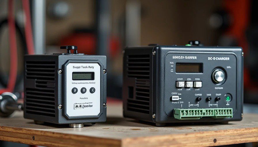
The first decision you need to make is what kind of charge management device to use. There are two main options: a Voltage-Sensitive Relay (VSR) or a DC-DC charger.
Voltage-Sensitive Relay (VSR)
A VSR is a smart relay that connects the two batteries when the engine is running and disconnects them when the engine is off1. It senses voltage — when the alternator is charging (typically above 1.5V), the relay closes and both batteries charge. When the voltage drops (below about 12.8V), the relay opens and the batteries are isolated-.
Pros:
Simple and reliable-
Cost-effective
No voltage drop (it's a mechanical relay, not a diode)-
Works well with traditional alternators and AGM batteries1
Cons:
Doesn't condition the charge — it just passes alternator voltage directly
Not ideal for smart alternators (the kind that vary voltage based on load)
Not suitable for lithium batteries without additional hardware
DC-DC Charger
A DC-DC charger takes the alternator's output and converts it to the correct charging profile for your auxiliary battery. It provides multi-stage charging (bulk, absorption, float) and can handle different battery chemistries — AGM, flooded, or lithium.
Pros:
Provides correct charging profile for any battery type-
Works with smart alternators
Often includes solar MPPT input
Protects your alternator from excessive draw
Cons:
More expensive (often 50x the price of a VSR)-
More complex to install-
Generates some heat — needs airflow
Which one should you choose?
If you're running a traditional alternator, AGM batteries, and your auxiliary battery is under the hood with short cable runs, a VSR is a solid, budget-friendly choice.
If you're running a modern vehicle with a smart alternator, lithium batteries, or your auxiliary battery is located in the rear of the vehicle with long cable runs, go with a DC-DC charger1.
I run a DC-DC charger on my 4Runner because I have lithium batteries and I want the correct charging profile. It costs more, but it's worth it for the peace of mind.
Wire Gauge: The Number That Matters Most
This is where most DIY installs go wrong.
The cable that connects your starter battery to your auxiliary battery carries a lot of current — potentially hundreds of amps if you're running a winch or inverter. If the cable is too small for the load, it gets hot. If it gets hot enough, the insulation melts, the wires short, and you have a fire--.
The rule is simple: size your cable for at least 150% of the maximum expected current.
Here's a rough guide:
Cable Gauge | Max Current (continuous) | Best For |
8 AWG | ~40A | 25A charger, both batteries in engine bay |
6 AWG | ~55-75A | Aux battery in tub or rear, loads under 40A |
4 AWG | ~8500A | Inverters over 600W, long cable runs |
2 AWG | ~1050A | Winch loads, high-current systems |
But here's the catch: wire gauge also depends on length. A 4 AWG cable that's feet long can handle more current than a 4 AWG cable that's 20 feet long. Longer cables have more resistance, which means more voltage drop and more heat.
The rule of thumb: keep your cable runs as short as possible. If your auxiliary battery is in the rear of the vehicle, you need heavier cable than if it's under the hood.
What I use: On my 4Runner, the auxiliary battery is in the rear cargo area. I run 2 AWG welding cable from the starter battery to the DC-DC charger, and 2 AWG from the charger to the auxiliary battery. Welding cable has fine strands (more flexible) and is rated for higher temperatures than standard automotive cable-. I use marine-grade tinned copper cable where possible — it resists corrosion better than bare copper.
Fuse Placement: The Fire Prevention Rule
Here's the single most important rule of dual-battery wiring:
Fuse every positive cable at both ends.
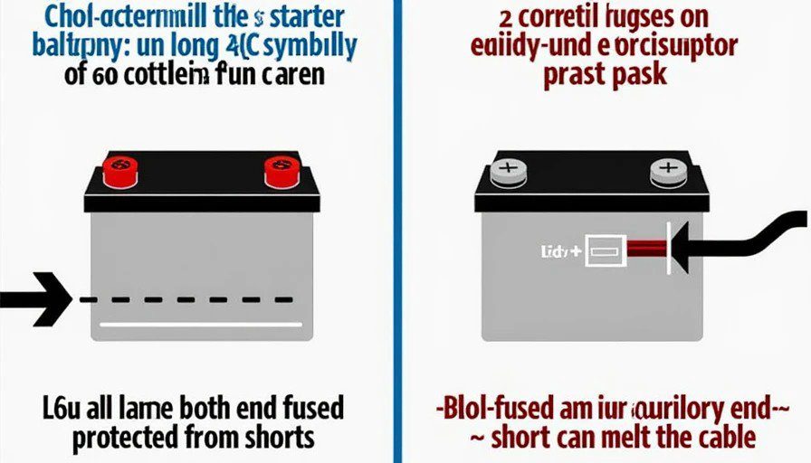
Why? Because with two batteries, your system is "live" at both ends. If you only fuse one end and a short occurs, the other battery can still feed current into the shorted wire. If the wire runs 20 feet under your truck and the fuse is at one end, you've got 20 feet of unfused wire that can turn into an arc welder.
The rule is simple: place a fuse or circuit breaker within a few inches of each battery's positive post. The normal spec is within 18 inches-.
Where the fuses go:
Starter battery to isolator/charger: Fuse within 18 inches of the starter battery positive post.
Isolator/charger to auxiliary battery: Fuse within 18 inches of the auxiliary battery positive post.
Auxiliary battery to distribution panel: Fuse at the battery end.
Any branch circuit: Fuse at the point where it connects to the main system.
What size fuse?
The fuse should be rated for the cable, not the load. The fuse's job is to protect the wire from melting. Size the fuse to the cable's ampacity, not the device you're powering.
For a 2 AWG cable, a 150A fuse is about right-. For 4 AWG, 10025A. For 6 AWG, 60-80A-.
What I use: I use ANL fuses for the main battery cables — they're robust and handle high current well. For branch circuits, I use a Blue Sea fuse block with ATC fuses. Every positive cable in my system is fused at both ends.
Grounding: The Overlooked Failure Point
Grounding is where I see the most mistakes.
The auxiliary battery needs a solid ground connection. The ground path carries just as much current as the positive path. If the ground connection is poor, the system won't charge properly, and you'll get voltage drop and heat buildup.
The rule: Connect the auxiliary battery's negative terminal to the chassis ground, scraping paint to ensure metal-to-metal contact. Use the same gauge cable for the ground as you used for the positive-.
But here's the important part: the starter battery and auxiliary battery should share a common ground point-. If they don't, the isolator or charger may not sense voltage correctly, and the system won't work properly.
What I do: I run a 2 AWG ground cable from the auxiliary battery to a clean chassis ground point near the battery. I also run a separate ground strap from the chassis to the engine block to ensure a solid path back to the alternator-. I use dielectric grease on all ground connections to prevent corrosion.
The Mistakes I've Seen (and the Parts on My Wall)
I've collected a few casualties from bad dual-battery installs over the years. Here's what's hanging on the Parts Graveyard wall.
Mistake 1: Undersized Cable
The part: A melted 8 AWG cable that was used to connect a starter battery to an auxiliary battery 15 feet away. The owner was running a 50A DC-DC charger, and the cable got hot enough to melt the insulation.
The tag:
DATE: March 2024
LOCATION: Removed in the shop after a customer's system failure
PART: 8 AWG cable, melted insulation, copper exposed
FAILURE MODE: Thermal overload from undersized cable
CAUSE: 8 AWG cable on a 15-foot run with 50A of current. The cable was rated for 40A maximum, and it was pushed well beyond that.
LESSON: Size your cable for 150% of the maximum current, and account for length. Longer runs need heavier cable.
Mistake 2: No Fuse at the Auxiliary Battery
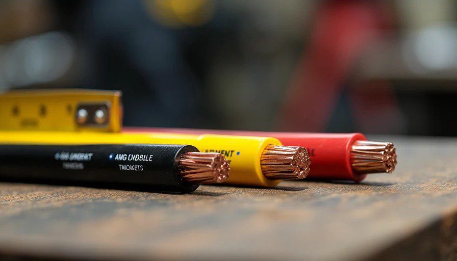
The part: A melted 4 AWG cable that shorted against the chassis under the rear of a 4Runner. The owner had fused the cable at the starter battery but not at the auxiliary battery. When the cable chafed through the insulation and shorted, the auxiliary battery fed current into the short from the unfused end.
The tag:
DATE: August 2024
LOCATION: Mojave Desert, California — trailside repair
PART: 4 AWG cable, burned insulation, melted copper
FAILURE MODE: Short circuit from cable chafing against chassis
CAUSE: No fuse at the auxiliary battery end. The fuse at the starter battery didn't protect the full length of the cable.
LESSON: Fuse every positive cable at both ends. A fuse only protects the wire between the fuse and the load — not the wire between the fuse and the battery.
Mistake : Poor Ground Connection
The part: A melted auxiliary battery terminal. The owner had connected the auxiliary battery's negative terminal to a painted chassis bolt. The paint prevented a good connection, creating resistance. The resistance generated heat, and the heat melted the battery terminal.
The tag:
DATE: November 2024
LOCATION: Removed in the shop after a customer's system failure
PART: Auxiliary battery negative terminal, melted plastic, deformed lead post
FAILURE MODE: Thermal damage from high-resistance ground connection
CAUSE: Ground cable connected to painted chassis surface. The paint prevented metal-to-metal contact.
LESSON: Scrape paint to bare metal for ground connections. Use dielectric grease to prevent corrosion. The ground path is just as important as the positive path.
Mistake 4: Mixing Battery Types
The part: A swollen AGM battery that had been connected in parallel with a flooded lead-acid battery. The two batteries had different charge profiles and internal resistances. The AGM was overcharged and the flooded battery was undercharged-.
The tag:
DATE: February 2025
LOCATION: Removed in the shop after a customer's system failure
PART: AGM battery, swollen case, cracked casing
FAILURE MODE: Overcharging from mismatched battery types
CAUSE: AGM and flooded batteries connected in parallel without proper charge management
LESSON: Don't mix battery types in a dual-battery system-. Use the same chemistry for both batteries, or use a DC-DC charger that can handle different profiles-.
Step-by-Step: How to Do It Right
Here's the installation process I use for every dual-battery system I build.
Step 1: Plan the Layout
Choose the battery location. Under the hood is the simplest, but not always possible. If the auxiliary battery is in the rear, plan your cable route carefully.
Measure the cable run. Positive and negative. Include the return path in your length calculation.
Calculate the maximum current. This is the alternator's output or the DC-DC charger's rating — whichever is higher-.
Size the cable. Use the chart above, accounting for length.
Choose the isolator or charger. VSR for simple systems, DC-DC for smart alternators or lithium.
Step 2: Mount the Battery and Components
Secure the auxiliary battery. Use a proper battery tray or mounting bracket. An unsecured battery can short against the vehicle frame or tip over-.
Mount the isolator or charger. Keep it within 00mm (about 12 inches) of the starter battery if possible. Ensure it has airflow for cooling.
Keep cables away from heat. Route cables away from exhaust manifolds, turbochargers, and other heat sources.
Step : Run the Cables
Run the positive cable from the starter battery to the isolator/charger, then to the auxiliary battery.
Run the negative cable from the auxiliary battery to a clean chassis ground point.
Use split loom or conduit to protect cables from abrasion.
Secure cables with zip ties every 00mm (about 12 inches).
Step 4: Install the Fuses
Install a fuse within 18 inches of the starter battery positive post-.
Install a fuse within 18 inches of the auxiliary battery positive post.
Use the correct fuse size for your cable gauge-.
Step 5: Ground the System
Scrape paint to bare metal at the chassis ground point.
Use the same gauge cable for the ground as the positive-.
Apply dielectric grease to prevent corrosion.
Ensure a common ground between the starter battery and auxiliary battery.
Step 6: Test the System
Reconnect the starter battery.
Check voltages: 12.6V at rest, 14.2V when charging.
Test the isolator or charger: verify it connects when the engine is running and disconnects when the engine is off.
Test the loads: run your fridge, lights, or other accessories and verify they draw from the auxiliary battery.
What I Run
On my 4Runner, I run a DC-DC charger with a lithium auxiliary battery in the rear cargo area.
The setup:
DC-DC charger: 25A unit with solar MPPT input
Auxiliary battery: 100Ah LiFePO4 (lithium iron phosphate)
Cable: 2 AWG welding cable from starter battery to charger, 2 AWG from charger to auxiliary battery
Fuses: ANL fuses at both battery ends, rated at 150A
Ground: 2 AWG ground cable from auxiliary battery to chassis, common ground with starter battery
Why lithium? It's lighter than AGM, charges faster, and can be discharged deeper without damage-. But it requires a DC-DC charger with a lithium profile-.
Why a DC-DC charger? My 4Runner has a smart alternator that varies voltage based on load. A VSR wouldn't charge the lithium battery correctly. The DC-DC charger provides the correct charging profile regardless of what the alternator is doing.
The Takeaway
A dual-battery system is one of the most useful upgrades you can make to an overland rig. It lets you run your fridge, lights, and accessories without worrying about a dead starter battery.
But it's also one of the easiest systems to screw up. Undersized cable. Missing fuses. Poor grounds. Mismatched batteries. I've seen all of them, and I've got the melted parts on my wall to prove it.
The rules are simple:
Size your cable for 150% of the maximum current.
Fuse every positive cable at both ends.
Ground properly — scrape paint, use the same gauge, share a common ground.
Choose the right isolator or charger for your battery type and alternator.
Don't mix battery types without proper charge management-.
Follow these rules, and your dual-battery system will work for years without drama. Ignore them, and you might end up with a melted cable, a dead short, or worse.
I've got the parts on the wall to prove it. You don't need them on yours.


No comments yet — grab the first one.